
BLEASS Peaks unites classic audio filtering with the spontaneous spirit of performance to deliver an entirely new class of creative filtering effects.
The plugin is built around BLEASS’ advanced multi-peak polyphonic filter design. When set to Internal control mode, this creates a single bell-filter curve containing up to 32 resonant peaks/notches. Details of the filter curve, such as the quantity, root frequency, and spread of the peaks/notches, are set parametrically, making it easy to shape the filter’s response and bring it to life via the plugin’s synth-style modulation sources.
BLEASS Peaks truly comes into its own when operating in MIDI mode. In this configuration, the filter’s root frequency is controlled via MIDI coming from live-played notes or a recorded track. Better still, BLEASS Peaks can generate up to eight such filters simultaneously, making this a true polyphonic filter.
MIDI control makes the filter fully playable and performable, opening up a whole new constellation of original and compelling filtering effects. Drum loops can be tuned to follow chord progressions, rhythmic harmonic pulses can be added to pads, arpeggios can be brought to life with complex frequency-shifting chorus effects… the creative possibilities are endless.
Additional colour and detail can be added to Peaks’ filtering via a set of five assignable Effects slots. These allow you to enhance the filtered sound with distortions, dynamics processors, delay, and even conventional low- and high-pass filters.
As with the filter itself, Peaks’ effects can be brought to life by the plugin’s various modulation sources, with each modulator mappable to up to four destination parameters. There are three LFOs, three envelopes triggered by the incoming audio plus a fourth triggered via MIDI, and four Macro controls. Alongside these internal modulators, the plugin also recognises various realtime MIDI CC and MPE sources.
Used as a conventional single-voice filter, BLEASS Peaks is at the top of its game, allowing easy-yet-deep control over the spectrum of your audio, and offering many ways to inject life and movement into the effect. Enabling MIDI control makes that advanced filter behave as a playable instrument, unshackling you from the limitations of conventional filtering and giving you direct hands-on control over the effect.
However you choose to use it, BLEASS Peaks is a uniquely creative, intuitive and fun tool for shaping, colouring, and injecting originality into your music.
FILTER TAB
The Filter tab is where you shape the core sound of BLEASS Peaks — it lets you configure the comb filter’s frequency, resonance, number of peaks/notches, and their distribution across the spectrum. You can also control how the filter sweeps through its range and set the boundaries within which the peaks operate.
INPUT GAIN
Use the fader to control the volume level of the incoming signal.
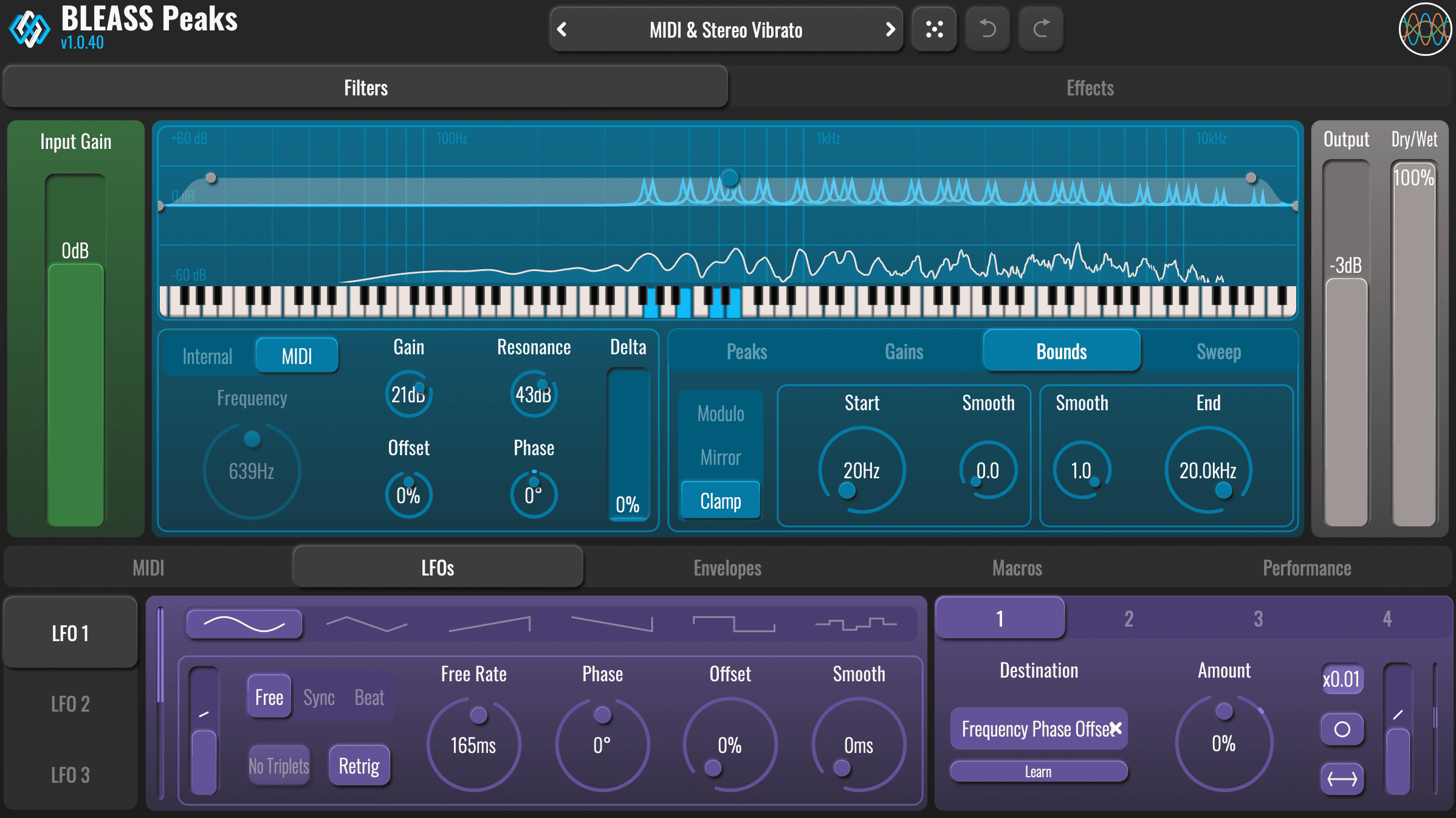
FILTERS VISUALISATION
This panel shows an interactive graphical representation of Peaks’ filter setup and activity.
The nodes shown on the panel provide alternative ways to control certain filter parameters. The nodes control the following parameters, which are explained in greater detail in the relevant section of this guide…:
– The blue node controls the filter’s main frequency and gain.
– The grey nodes control the cutoff frequency and slope of the filter’s Bounds.
When in MIDI mode, the graphical keyboard can be used to trigger the filter using the mouse (the keyboard is not interactive in the AUv3 version of the plugin).
The peaks and/or notches of the current filter curve are also shown. When in MIDI mode, the curve will only show when incoming notes trigger the filter.
FILTER CONTROL SOURCE BUTTONS
Choose between the filter’s Internal control mode and MIDI control mode.
FREQUENCY
When in Internal control mode, this dial sets the main frequency for the filter. The main frequency is the frequency of the first peak/notch, and is the basis from which any additional peak/notch frequencies are calculated.
This parameter is ignored when in MIDI control mode. In this mode, the main frequency is determined by incoming MIDI notes.
GAIN
Controls the filter’s master gain. Negative values will reverse the polarity of the filter’s peaks/notches – that is, peaks become notches and vice-versa.
RESONANCE
Controls the sharpness and bandwidth of the peaks/notches being generated by the filter. Low values create wide, gentle curves, whilst high values create narrow, sharp curves.
OFFSET
Applies an offset to the filter’s main frequency (Internal or MIDI). The frequency of additional peaks/notches are based on the main frequency so these are also impacted. An offset of 100% will set frequencies back to their initial position. You can modulate this parameter to create cyclic filtering movements.
PHASE
Applies equal-and-opposite frequency offsets to the left and right channels of the filter.
DELTA
Controls the prominence or intensity of the effect by subtracting the dry signal from the filtered signal. At 100% most of the non-resonant sound is cancelled out, leaving just the resonant peaks (or notches) of the comb filter.
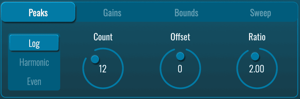
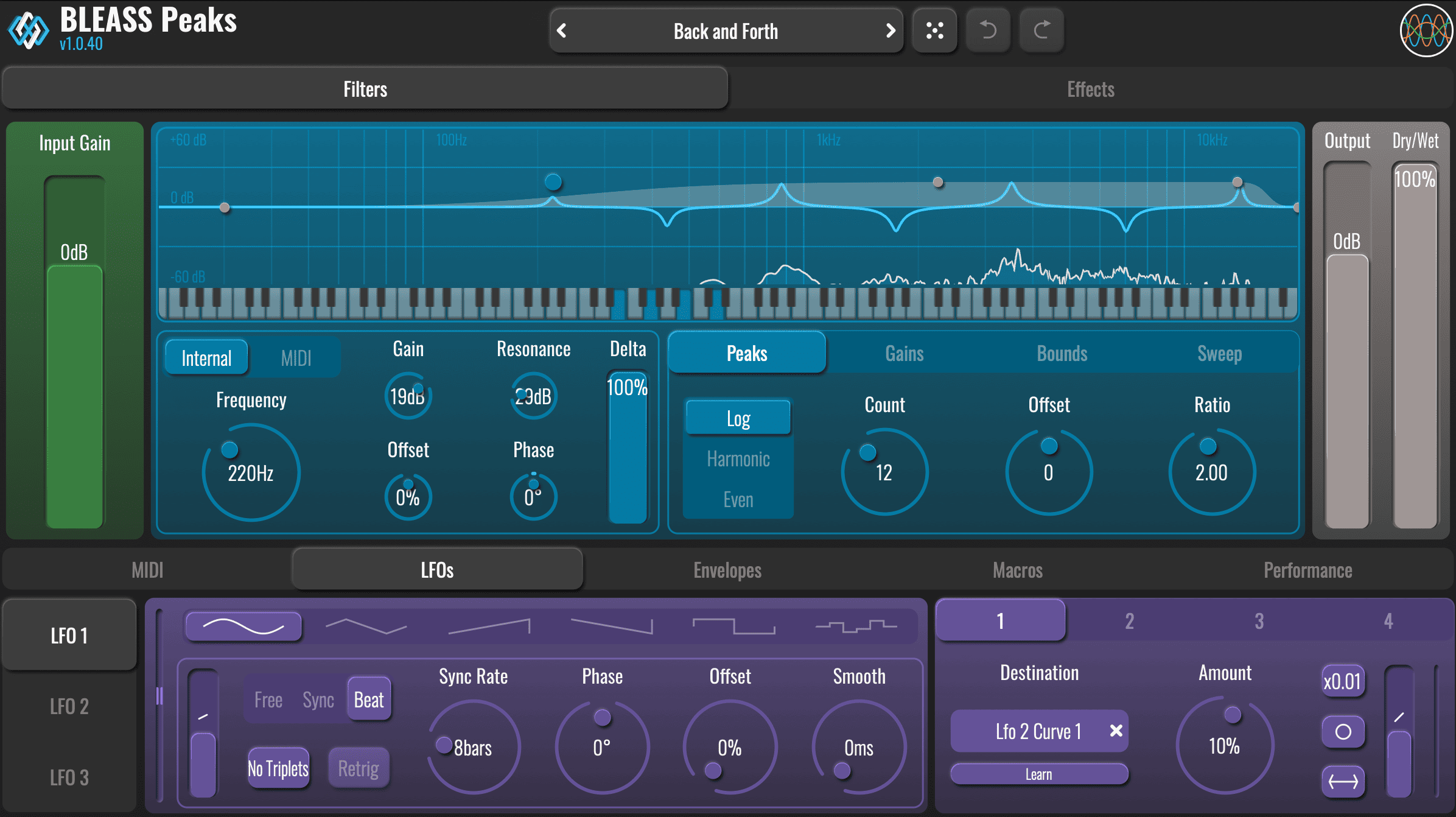
PEAKS PANEL
The Peaks Panel is where you control how many peaks/notches the filter creates and how their frequencies are distributed across the spectrum.
PEAKS MODE
These three options determine the way in which peak/notch frequencies are calculated from the main filter frequency:
In Log mode, the frequency of each peak/notch is a multiple of the previous peak/notch, with the multiplier being defined by the Ratio parameter.
F(n) = F(n-1)*ratio
For example, with a Ratio value of “2”, each peak/notch frequency will be double the previous one.
In Harmonic mode, the frequency of each peak/notch is a multiplication of the main frequency, the multiplier being defined by the Ratio parameter, and increasing with each successive peak/notch.
F(n) = F(0) * ratio * n
For example, with a Ratio value of “1”, the peaks will follow the harmonic series distribution
In Even mode, the overall bandwidth of the filter, as determined by the Bounds values (see below), is split into divisions that appear equally spaced on Peaks’ Filter Visualisation. Note that the visualisation’s scale is logarithmic, and so these visually equidistant peaks/notches do not share the same absolute frequency offset from each other.
Note that the peak/notch frequencies may also be impacted by other parameters.
COUNT
Sets the number of peaks/notches that will be created by the filter. A setting of “1” means only the filter’s main frequency is used.
Increasing the value creates additional peaks/notches.
OFFSET
Shifts the frequency of each peak/notch to the frequency of the next peak/notch. The offset “wraps” within the overall frequency range defined by the Bounds settings (see below).
RATIO
Sets the multiplier used to calculate peak/notch frequencies in Log and Harmonic modes. Is not used in Even mode.
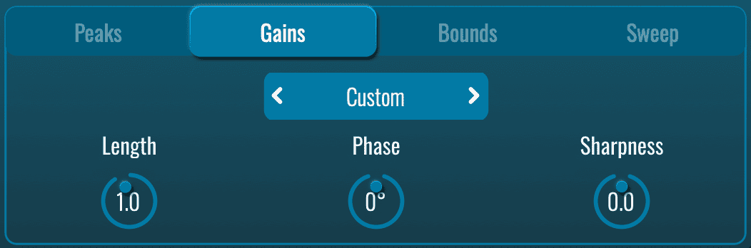
GAINS PANEL
The Gains Panel is all about controlling the polarity pattern of your peaks and notches — essentially, which filter points boost the signal and which ones cut it.
POLARITY SELECTOR
This setting controls the polarity of the peaks/notches that are produced by the filter.
Assuming a positive value is set for the filter’s gain:
Unipolar results in only peaks being produced
Bipolar alternates between producing peaks and notches
Tripolar produces a pattern where each peak is followed by two notches
Custom enables the Gains Panel’s dials, allowing the user to define the pattern of peaks and notches that will be produced
CUSTOM POLARITY CONTROLS
When you switch the Polarity Selector to Custom, three extra knobs appear: Length, Phase, and Sharpness.
These knobs let you design your own repeating pattern that decides, for each peak or notch in the bell filter, whether it becomes a boost (peak), a cut (notch), or something in between, and how strong that boost or cut is.
Think of it like drawing a simple wave shape that repeats across your filter’s frequencies:
Length – How many steps are in your repeating pattern before it starts over. Short Length (e.g. 2 or 3) = fast back-and-forth between peaks and notches. Longer Length = more room for interesting sequences (peak → notch → small peak → big notch…).
Phase – Where the pattern starts. Turn this knob to shift the beginning so the very first frequency gets a peak, a notch, or anything you want.
Sharpness – How sudden or smooth the changes are between boosts and cuts. Low Sharpness = soft, gentle curves (sounds smoother and more natural). High Sharpness = hard, sharp switches (sounds punchier, more digital or aggressive).
This Custom mode is great for creating unique, one-of-a-kind filter shapes that regular polarity options can’t do, perfect if you want weird vocal-like effects, pulsing harmonics, or anything extra creative.
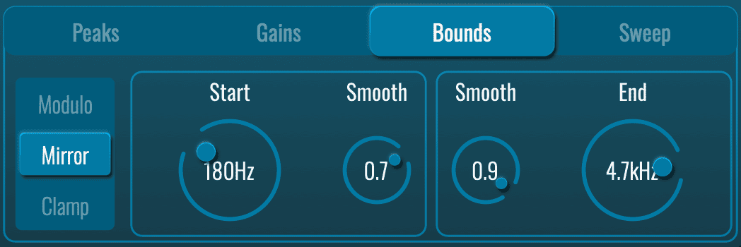
BOUNDS PANEL
The Bounds panel defines the frequency range within which the filter’s peaks and notches operate.
BOUNDS MODE
Determines what happens when the frequency of a peak/notch exceeds the limits set by the Bounds Start and End frequencies.
Modulo causes out-of-bounds frequencies to loop back around to the other end of the bounds. For example, a frequency that exceeds the Bounds End will wrap to the Bound Start frequency; similarly, a frequency that falls below the Bound Start will wrap to the Bound End frequency.
Mirror causes frequencies to reflect back from the Bounds Start and End frequencies.
Clamp removes frequencies that push above or below the Bound Start and End frequencies.
START
Sets the starting frequency of the filter’s operational range.
END
Sets the ending frequency of the filter’s operational range.
SMOOTH
Both Start and End dials have their own Smooth setting. This controls the steepness of the attenuation slope associated with the Start and End frequencies. Low values create a sharp cutoff at the Bounds frequencies; higher settings will cause filter frequencies to taper-off more smoothly as they approach the Bounds frequencies.
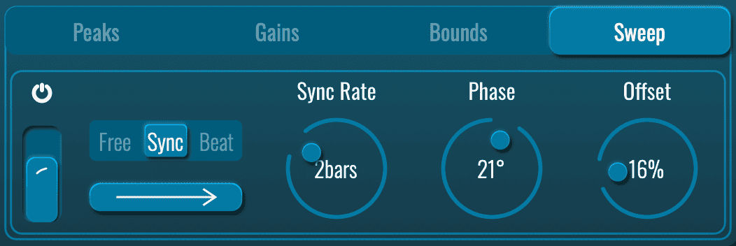
SWEEP PANEL
The peak/notch frequencies being produced by the filter can be automatically swept through the range defined by the Bounds settings. The parameters included on this panel control this effect.
SWEEP ON/OFF
Enables or disables the Sweep effect.
SWEEP CURVE FADER
Applies a ramping effect to the rate at which frequencies are swept.
The middle position produces a constant rate of motion
Higher settings cause the sweep to decelerate from a fast start
Lower settings cause the sweep to accelerate from a slow start.
SWEEP SYNC MODE
Determines whether the Sweep effect is free-running or synchronised to the host DAW.
In Free mode the timing of the sweep effect is set in terms of absolute seconds
In Sync mode the timing of the sweep effect is locked to the tempo of the host DAW
In Beat mode the timing of the sweep effect is locked to the tempo of the host DAW, and the progress of the effect is synchronised to the host’s bar and beat position.
SWEEP DIRECTION
Click the button to toggle the Sweep effect between running forward (increasing filter frequencies) or backwards (decreasing filter frequencies).
FREE / SYNC RATE
Sets the time duration of the Sweep effect.
When Sync Mode is set to “Free”, Rate is expressed in terms of absolute seconds
When Sync Mode is set to “Sync” or “Beat”, Rate is expressed in terms of bars or fractions of a beat.
PHASE
Creates a stereo effect by offsetting the left and right channel progress of the Sweep effect.
OFFSET
Offsets the starting point of the Sweep effect. For example, a setting of “50%” will cause the effect to start halfway through its range whenever it’s retriggered.
MIDI TAB
The parameters shown when this tab is selected allow you to control how Peaks responds to incoming MIDI data.
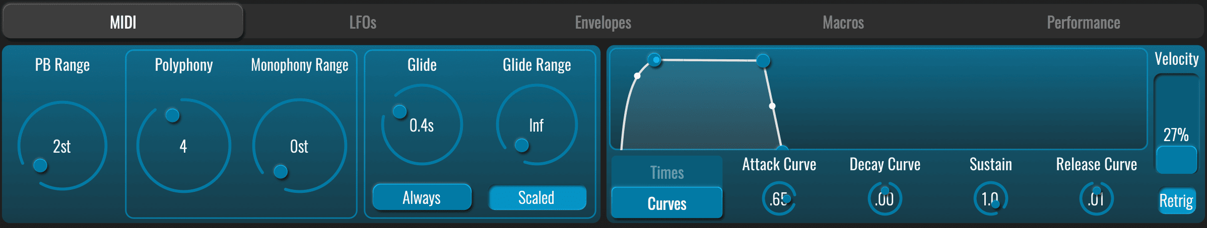
PB RANGE
Defines the maximum range of response to incoming MIDI Pitch Shift messages
POLYPHONY
Defines the maximum number of notes that can be played simultaneously and therefore the number of filter voices that are created before the oldest note(s) are stopped to make way for additional notes.
MONOPHONY RANGE
Defines the maximum pitch interval (from the active note) within which an incoming note will steal the existing voice instead of triggering a new one.
If a new note is played and its pitch is within a certain range of a note that’s already being played, that existing note’s voice can be stolen by the new note. The Monophony Range determines how close those new and existing notes have to be to trigger this behaviour.
GLIDE
Peaks can apply a portamento effect to incoming MIDI notes, shifting the pitch smoothly from one to another.
The Glide value determines the length of that glide, in seconds.
Glide Range : The pitch range of the portamento glide can be limited, useful to avoid very large swings in filter frequency. The Glide Range control defines the maximum number of semitones that a glide can cover, measured as an offset from the destination note.
Glide Mode determines when the portamento effect is applied.
In Always mode, every note will glide from the previous one, even after a break in playing.
Scaled mode affects how the Glide time is interpreted: when on, the glide time represents the duration needed to travel 12 semitones, meaning larger intervals take proportionally longer; when off, the glide time is constant regardless of the interval between the two notes.
ENVELOPE
This envelope is applied to each incoming MIDI note, shaping the volume of the resulting filter. The envelope uses a standard AHDSR model, and can be edited either by dragging the nodes and curves on the graphic display, or via the dials located below it.
- The Times/Curves button toggles the dials between showing the length of each phase of the envelope, and the curves applied as the envelope progresses through its stages.
- The Velocity fader allows the velocity of incoming notes to control the magnitude of the envelope, and thereby the intensity of the resulting filter effects.
- The Retrig button determines whether the envelope continues when legato notes are received (that is, a new note is played before the previous note is released), or is retriggered for every incoming note-on message.
MIDI ROUTING
As an effect processor, BLEASS Peaks does not automatically receive MIDI input. However, every instance of the plugin creates its own MIDI destination within a DAW project.
To make use of this, simply create a MIDI/instrument track and route its output to the BLEASS Peaks instance you want to control.
You can then use this track to direct live MIDI input from your keyboard or controller to BLEASS Peaks, as well as to record that MIDI input for playback into the plugin.
> Watch this tutorial < to know how to route MIDI to BLEASS Peaks in your DAW!
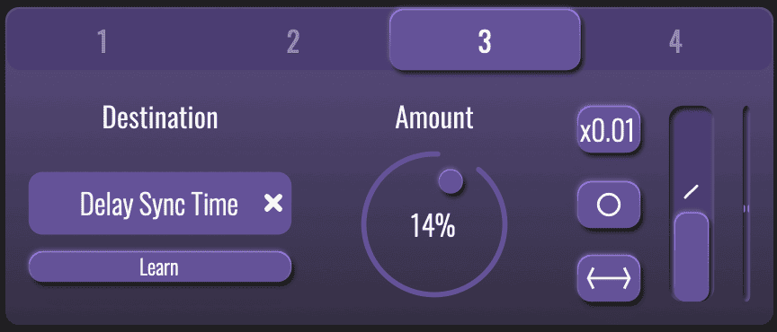
ROUTING PANEL
Each of BLEASS Peaks’ modulators can be routed to up to four destination parameters. The details of each routing is controlled from a modulator’s routing panel. This panel works identically for each modulator.
NUMBER BUTTONS
Selects each of the four possible routings for the modulator.
DESTINATION
Specifies the parameter that will be modulated via the routing.
LEARN
This button provides an alternative method for selecting a destination parameter. Simply click the button, causing it to pulse, and then click on the parameter you wish to modulate.
AMOUNT
Determines how strongly the modulator will impact on the destination parameter.
X0.01 BUTTON
Reduces the strength of modulation being sent to the destination by a factor of 100. This makes it easy to create very small fluctuations in the destination parameter’s value.
MONO/STEREO BUTTON
- In Mono mode (single circle), the modulator’s output is applied equally to both left and right channels.
- In Stereo mode (double circle), the left and right values are 180° out of phase with each other. This means that when the left channel’s value is rising the right channel’s value will be falling, and vice versa.
POLARITY BUTTON
- In Unipolar mode (arrow facing right), the modulation is summed with the destination parameter’s value. When in Stereo mode, the left channel receives a positive value and the right channel receives a negative value (this can of course be reversed by using a negative Amount value).
- In Bipolar mode (arrow facing in both directions), the modulation fluctuates around the destination parameter’s value.
CURVE FADER
Adds an acceleration or deceleration to the rate at which the modulation value changes.
MODULATION METER
The meter shown on a Routing Panel visualises the actual strength of modulation being sent to the destination parameter, taking into account all of the routing’s settings.
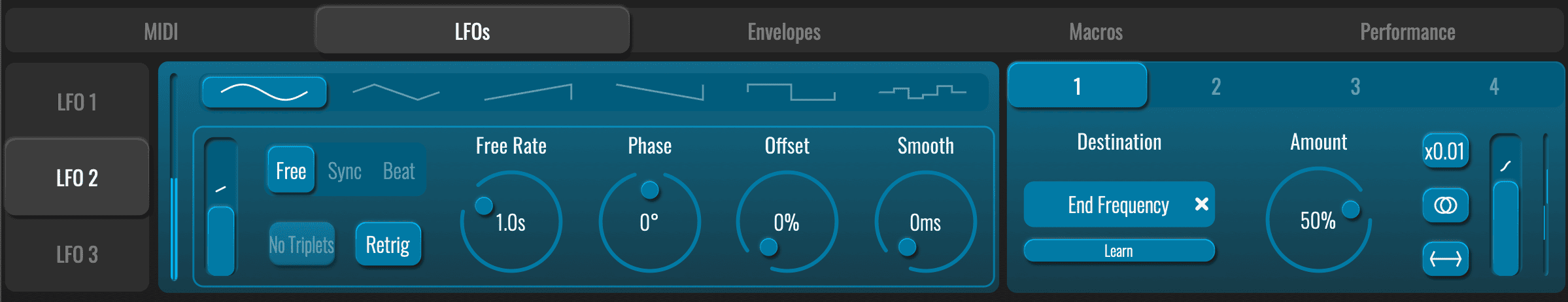
LFO TAB
BLEASS Peaks features three LFOs (Low Frequency Oscillators) for creating repeating, cyclic modulations. The buttons shown to the left of the panel allow you to select which LFO is currently being edited.
WAVEFORM
Specifies the waveform that the LFO will use.
MODULATION METER
Visualises the LFO’s output.
CURVE FADER
Warps the shape of the LFO’s waveform.
Has no effect when in the central position.
When in an upper position, slows the LFO waveform’s onset phase and accelerates its falloff phase.
When in a lower position, accelerates the LFO waveform’s onset phase, and slows its falloff phase.
SYNC MODE
Free uses internal timing for the LFO.
Sync synchronises the LFO to the host DAW’s tempo.
Beat synchronises the LFO to the host DAW’s tempo and bar position.
NO TRIPLETS
When enabled, any triplet value selected for the LFO Rate (1/3, 1/6 etc.) will be ignored. Not available in Free sync mode.
RETRIG
Restarts the LFO whenever a new MIDI note is played.
SYNC RATE
Sets the time taken for the LFO to complete one cycle of its waveform. The Rate is expressed as milliseconds and seconds when in Free sync mode, otherwise it is expressed in terms of note length.
PHASE
Creates a phase offset between the left and right channels of the LFO.
OFFSET
Creates a global phase offset for the LFO.
SMOOTH
Smooths the rate at which the LFO’s output value changes.
This is most useful when used with square, sawtooth and sample-and-hold LFO waveforms.
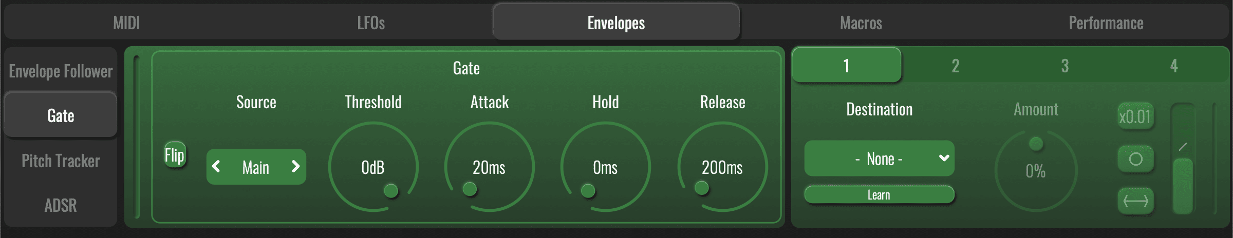
ENVELOPES TAB
There are four different types of envelope modulator included in BLEASS Peaks, with each working differently to the others. The buttons to the left of the display allow you to select the envelope you wish to edit.
ENVELOPE TYPES
Envelope Follower tracks the amplitude of incoming audio and translates this into the modulator’s output.
Gate tracks the amplitude of incoming audio. When the audio amplitude passes over a threshold value the envelope is triggered.
Pitch Tracker analyses the pitch of the incoming audio and translates this into the modulator’s output.
ADSR creates a standard AHDSR envelope triggered by incoming MIDI notes.
ENVELOPE SOURCE
The Envelope Follower, Gate and Pitch Tracker envelopes all feature a Source option.
When set to “Main”, it is the main audio signal being processed by the plugin that drives the envelopes.
When set to “Sidechain”, the envelopes are driven by the signal arriving at the plugin’s sidechain input. The method for routing signals to this sidechain input varies between DAWs, so consult your DAW’s documentation for information on configuring sidechains.
ENVELOPE MODULATION METER
Visualises an envelope’s output.
ENVELOPE FOLLOWER CONTROLS
Curve Fader
Warps the shape of the Envelope Follower’s attack and release stages.
Has no effect when in the central position.
When in an upper position, accelerates the attack stage and slows the release stage.
When in a lower position, slows the attack stage and accelerates the release stage.
Gain
Sets the sensitivity of the follower. Higher settings will result in envelopes of a higher magnitude.
Attack
Controls the time taken for the envelope follower to react to an incoming change in amplitude. Using low values results in an envelope that closely follows the amplitude of the incoming audio, whilst higher settings will smooth out sudden jumps but may cause the envelope to seem to lag behind the audio’s dynamics.
Hold
Sets the length of the envelope’s hold phase, which is triggered following the attack phase. Lower settings will cause the envelope to more closely follow the audio’s changing volume, whilst higher settings will soften the impact of sudden volume drops but may cause the envelope to seem to lag behind the audio’s dynamics.
Release
Sets the time taken for the envelope to return to a resting state after the hold time has expired.
GATE CONTROLS
Flip
Switches the envelope’s polarity. In standard mode, the envelope’s output value starts at zero and is increased when the envelope is triggered. When Flip is enabled, the envelope’s output value starts at maximum and is ducked when the envelope is triggered.
Threshold
Sets the amplitude at which the incoming signal will trigger the Gate envelope.
Attack
Defines the time taken for the envelope to reach its full output value after the Threshold has been exceeded.
Hold
Defines the amount of time the envelope will hold its full output value following the Attack phase.
Release
Defines the amount of time taken for the envelope to return to minimum following the Hold phase.
PITCH TRACKER CONTROLS
Smooth
Time taken after a pitch value change to reach the new value. Defines the time taken for the envelope to reach its new value following a pitch change.
Low Limit
Defines the lowest note that the Pitch Tracker will listen for and respond to. This also then acts as a lower limit for the generated modulation value.
High Limit
Defines the highest note that the Pitch Tracker will listen for and respond to. This also then acts as an upper limit for the generated modulation value.
ADSR ENVELOPE
ADSR creates a standard AHDSR envelope triggered by incoming MIDI notes. Its controls are identical to the MIDI Tab’s envelope, described above.
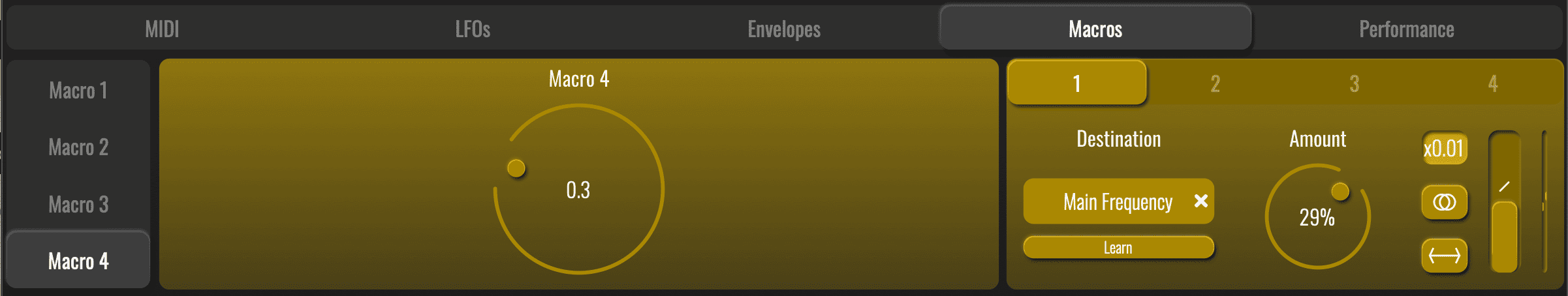
MACROS TAB
BLEASS Peaks has four Macro controllers, each allowing you to modulate up to four destination parameters via a single rotary control. Use the buttons to the left of the panel to select the Macro you wish to configure.
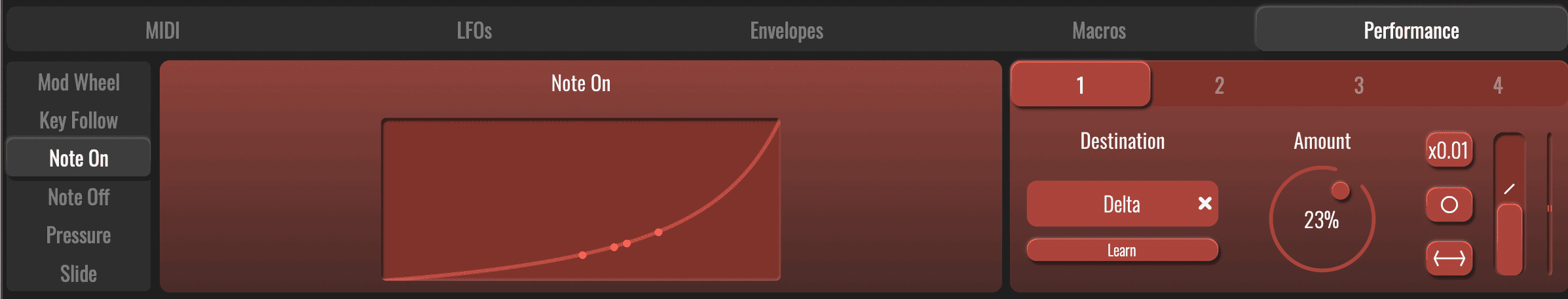
PERFORMANCE TABS
The Performance Tab allows MIDI note, CC and MPE events to be used as modulation sources for the plugin.
Use the buttons to the left of the panel to select the MIDI event you wish to configure.
RESPONSE CURVES
Each MIDI event type shows a response curve graph. Simply drag on this graph to shape this curve.
The curve shown for Key Follow includes a keyboard graphic.
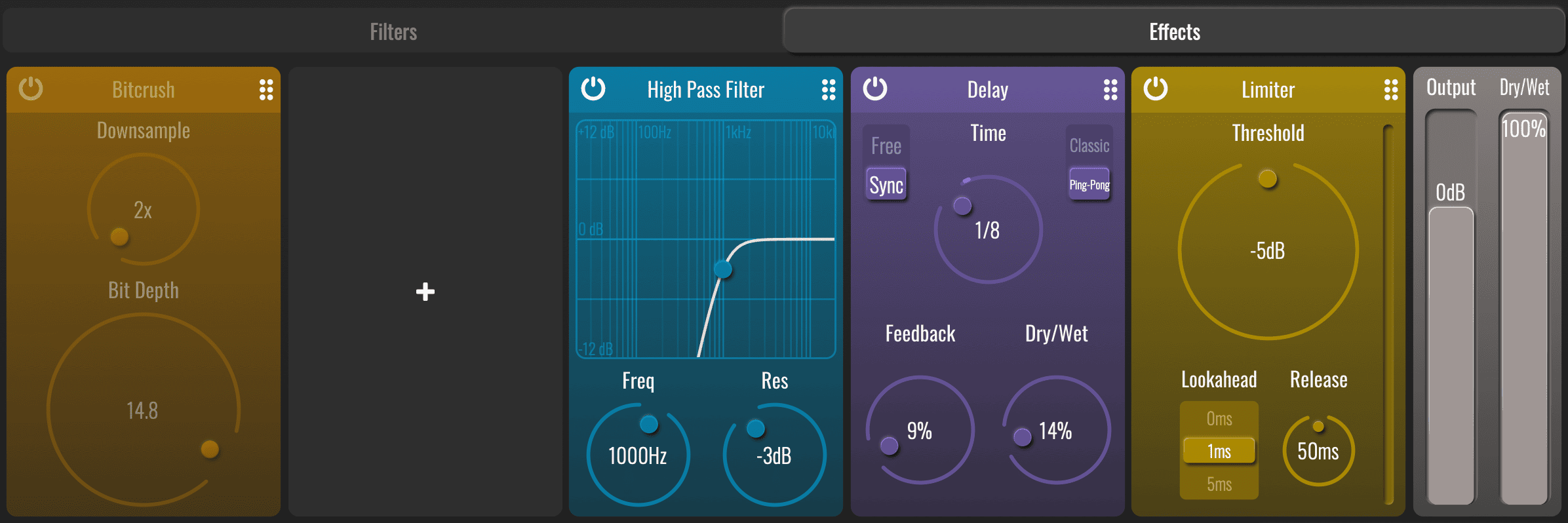
EFFECTS TABS
BLEASS Peaks includes five FX processing slots into which a range of different processors can be loaded. To load a processor, simply click on a slot and choose an option from the menu that appears. Each processor can only be used once in a patch.
IMPORTANT NOTE: Filters can produce unexpectedly high volume levels, and so we have included a Limiter as the final processor in all factory presets, including the Default preset provided as a starting point for new patches. We strongly recommend you keep this limiter in place and enabled at all times.
DISTORTION
Use this processor for adding classic distortion and overdrive effects to the filtered sound. Choose from three different distortion styles, and use the Input and Output dials to control the strength of the distortion effect.
COMPRESSOR
The Compressor is perfect for smoothing-out dynamic changes in the sound whilst preserving short snappy transients. The processor features familiar controls and incorporates a Gain Reduction meter that shows the processor’s activity.
LIMITER
The Limiter is best suited to catching and controlling short, sudden volume peaks, saving your mixes from clipping and your speaker from ripping.
BITCRUSH
This processor emulates the impact of reducing digital bit depth and sample rate. The distortions this produces can range from subtle dirtiness to full-on destruction.
DELAY
This classic Delay processor adds repeats to the signal, and can run freely or be synchronised to your DAW.
UTILITY
This processor provides panning and gain controls. These are most useful when you want to apply modulation to the position and or volume of the sound.
HIGH PASS / LOW PASS
Applies a resonant high-pass or low-pass filter to the signal chain. Either drag in the graph or use the dials to configure the effect.
TUTORIALS & REVIEWS: